Our company has rich experience in manufacturing high velocity relief valve. Recently, we improve the manufacture of pure gravity high velocity relief valve under the support of some institutes of ship design and colleges.
Our company researched, designed and manufactured the CF-type high velocity relief valve is the new generation, which has approved by the state administrative organs about the test and type of pressure/vacuum valve. At present, high velocity relief valves, which manufactured by our company has been tested, there are: 1. fire-proof test; 2. re-burning test; 3. frozen test; 4. corrosion test; 5. flow rate and performance test. The valve will open only for the system pressure reach to the open pressure steadily, because of its special design. Generally speaking, one of the most advanced high velocity relief valve that is adopted in the world is the valve, which can lessen pipe diameter and decrease the vapor loss during the navigation. Our products not only meet to the IMOMSC/Circ.1009 circulars, reach to the requirements of ISO STANDARD 15364, but also improve the mechanical performance of high velocity relief valve to a higher level. In other words, there is no pounding phenomenon, no flutter or ripple when open or close it, or increase or decrease the pipe pressure, so that there is no re-burning phenomenon.
II. Basic structure and main parts and fittings of CF-type high velocity relief valve

II. 2 Main size parameter of CF-type high velocity relief valve, see table 1
table 1
| 8 |
250 |
320 |
350 |
395 |
460 |
730 |
12XФ22 |
| 7 |
200 |
258 |
295 |
340 |
455 |
730 |
8ХФ18 |
| 6 |
150 |
202 |
225 |
265 |
385 |
670 |
8ХФ18 |
| 5 |
125 |
178 |
200 |
240 |
380 |
665 |
8ХФ18 |
| 4 |
100 |
148 |
170 |
210 |
285 |
485 |
4ХФ18 |
| 3 |
80 |
128 |
150 |
190 |
285 |
460 |
4ХФ18 |
| 2 |
65 |
110 |
130 |
160 |
255 |
410 |
4ХФ14 |
| 1 |
50 |
90 |
110 |
140 |
255 |
410 |
4ХФ14 |
| serial No. |
DN |
D |
D1 |
D2 |
L |
H |
assembly hole |
Remarks: flange executive standard: GB2501-89, DN50-DN150, nominal pressure is 0.6Mpa; DN200?DN250, nominal pressure is 1.6Mpa(is equal to ISO2084-1974?ISO2441-1975)
II. 3 Main parts and fittings of CF-type high velocity relief valve, see table 2.
table 2
| serial No. |
descripton |
quantity |
material |
remarks |
| 1 |
P-valve base |
1 |
ZG200-400 |
|
| 2 |
water nozzle |
1 |
0Cr19Ni9 |
|
| 3 |
P-valve seat |
1 |
0Cr19Ni9 |
|
| 4 |
P-valve disc |
1 |
0Cr19Ni9 |
|
| 5 |
matching block |
1 |
0Cr19Ni9 |
|
| 6 |
P-valve boby (A) (B) |
1 |
ZG200-400 |
|
| 7 |
condukting machine |
1 |
0Cr19Ni9 |
|
| 8 |
handle |
1 |
0Cr19Ni9 |
|
| 9 |
V-valve boby |
1 |
ZG200-400 |
|
| 10 |
matching block |
1 |
0Cr19Ni9 |
|
| 11 |
V-valve disc |
1 |
ZG0Cr19Ni9 |
|
| 12 |
V-valve seat |
1 |
ZG0Cr19Ni9 |
|
| 13 |
flame screen |
1 |
0Cr19Ni9 |
|
| 14 |
flame screen gland |
1 |
ZG200-400 |
|
| 15 |
nameplate |
1 |
cooper |
|
| 16 |
climbing pole |
1 |
0Cr19Ni9 |
|
| 17 |
air-freeing cover or V-valve cover |
1 |
ZG200-400 |
|
Remarks: about the body material, ship-owner can adopt cast steel, 304 cast, 304L cast or 316L cast.
III. Installation of high velocity relief valve
Each valve will be provided as a whole, and each valve is adjusted and tested so that the working pressure of pressure valve and the open pressure of vacuum valve reach to designed standard. Workers only need to connect each flange of valve to ventilating pipe of cargo tank by bolt before operate.
IV. Operation of high velocity relief valve
IV. 1 Oil loading: pressure valve of CF-type high velocity relief valve is under operation. Before loading oil, the handle must be shifted to upper in clockwise direction through shift fitting 8, lift up the valve kits and then shift back, the valve kits can fall down so as to check the flexibility of valve kits.
IV. 2 Oil unloading: vacuum valve of CF-type high velocity relief valve is under operation. Before unloading, the climbing pole shall lift up the valve and then drop by fitting 16, do it some times so as to check the flexibility of the valve.
V. Installation of high velocity relief valve
It shall adopt the following maintenance and repair terms about the high velocity valve according to regulations: the valve kits must be maintained and repaired after 6 months so as to keep its normal performance. Valve kits also shall be disassembled for cleaning.
It shall be maintained and cleaned if it loads cargos frequently or the cargos are diversity.
To maintain and repair the valve:
5.1 disassemble the pressure valve for cleaning:
5.1.1 assemble the bolt (hex socket cap screw) on the top of fitting 7, lift up fitting 7 conducting machine.
5.1.2 assemble the connection bolt (hex socket cap screw or wing screw) of fitting 6, lift up fitting 6 P-valve body, clean the hole of it.
5.1.3 lift up valve pole on the fitting 4 and fitting 5, clean the P-valve body. Especially, the connection space between fitting 3 valve seat and fitting 4 valve disc, check if there is damage or flaw, and clean the hole of P-valve base.
5.1.4 fitting 4 and fitting 5 is a combination parts, do not loose or disassemble the set screw when cleaning;
5.1.5 all disassembled fittings shall keep separately, the valve body cannot operate smoothly if there is any damages;
5.1.6 assemble the fittings in opposite after checking and cleaning. Check it follow words which mentioned in the 4.1;
5.2 disassembling and cleaning procedures of vacuum valve
5.2.1 disassemble the wing screw and fastened bolt on fitting valve cover, lift up the valve cover;
5.2.2 lift fitting 10 and 11, take the fitting 11 V-valve disc out of valve body for cleaning. At the same time, clean and repair the interior of valve, especially the sealing space of valve. It also should check whether there is any damages or flaws on the connection space between fitting 11 and fitting 12.
5.2.3 general speaking, clean the dust on the flame screen from exterior. It only need to disassemble fitting 14 connection screw for taking the flame screen out, then clean it;
5.2.4 assemble the fittings in opposite after checking and cleaning. Check it follow the words which mentioned in the 4.2; check it first and then fix fitting 14 valve cover is also ok.
5.3 attention
5.3.1 the disassembled fittings shall put on the soft mat reasonably, and disassembled follow the procedure strictly;
5.3.2 use gauze with detergent for cleaning, and clear the dirt away from valve body.
5.3.3 check the valve; it must be sent to the manufacturer for repairing if it cannot performance smoothly;
5.3.4 the manufacturer adjusted and tested the open pressure of the vacuum valve and kits of pressure valve strictly, it must be sent to the manufacturer for adjusting the open pressure if it is necessary.
VI. High velocity relief valve with air-freeing cover
VI. 1 Main purposes of air-freeing cover
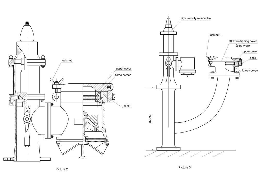
The valve will automatically open and eject to the upper of deck with the speed of 30m/s while the freeing gas in the tank reach to the open pressure of high velocity relief valve. The inner pressure of the tank cannot automatically open the high velocity relief valve while cleaning, exhausting. It need a manual device for its ventilating, such ventilating device is a air-freeing cover. It can be installed in the V-valve body of high velocity relief valve (see Picture 2), or be installed separately in the branch pipe of high velocity relief valve (see Picture 3).
Generally, the gas exhausted from air-freeing cover is incombustible. The air-freeing cover shall be closed when the ship navigating or loading for the working pressure is too low (less than 2.0 Kpa) and the flow rate is less than 20m/s.
As a fire arrester to prevent the pipe end from deflagrating, the air-freeing cover has been tested according to the regulations of EN12874-2001 and MSC/circ.667.
VI. 2 Main structure of air-freeing cover
The air-freeing cover is installed in the vacuum valve by bolt. it is composed of flame screen, shell and upper cover. (To see Picture 2).
VI. 3 Usage and maintenance of air-freeing cover
Ventilate the tank: loose the lock nut, lift up the upper cover and turn it to the vertical direction, then do the cleaning;.
The lock nut, hinge and flame screen is made of high quality stainless steel, keep its cleanness during operation, and clean it regularly.
Clean the interior of vacuum valve: disassemble the connection bolt and move the air-freeing cover, then do the cleaning.
List of Main Performance and Specifications
I. Manufacture and experimental basis:
IMO.MSC/Circ.677 Revised Standards of Designing, Testing and Installation the Device that can Stop the Flame into the Liquid Cargo Tank;
ISO15364: 2000 Pressure/Vacuum Valve for Cargo Tank;
IMO.MSC/Circ1009 Amendment about Revised Standards MSC/Circ.677 of Designing, Testing and Installation the Device that can stop the Flame into the Liquid Cargo Tank;
Section 5, Chapter 1 of Rules and Regulations for the Construction and Classification of Steel Ships 2001;
EN12874-2001, Performance Requirements, Testing Methods and Usage Scope of Flame Arrester;
Article 59, Chapter 11-2 of the International Convention for the Safety of Life At Sea, 1997 (SOLAS)
II.Main specification:
CF50, CF65, CF80, CF100, CF125, CF150, CF200, CF250
III.Main performance:
III.1.fire-resistance test and re-burning test on pressure valve and vacuum valve;
III.2.open and close the pressure valve and vacuum valve in the operating pressure range;
III.3.It must keep tightness of the shell of valve body from main pressure zone to main valve seat;
III.4.It must keep the shell, fitting and seal can bear the maximum pressure and temperature under normal working conditions and test its pressure according to the standard;
III.5.the design of interior structure of pressure/vacuum valve, it can disassemble when check, clean, maintain and change the interior fittings. If disassemble the whole device from system, it may appear some mistakes;
III.6.the equipment shall be operated under the normal temperature, if the equipment is icing, it will be operated after break the ice through using the manual device;
III.7.the valve disc, main axis of valve seat, flame screen shall use the seawater resistant, liquid resistant and vapor proof material; non-sealing fittings shall use the non-combustible materials; and the shell, bolts, washers and etc. shall use the material which meet to the national standard and do the anti-corrosion treatment;
III.8.pressure valve and vacuum valve shall be operated under the standard testing pressure.
IV. Main structure and working principle:
4.1 Main structure:
Serial high velocity relief valve adopts standardized design, each fittings and parts are standardized so that they can interchange and use for all purpose.
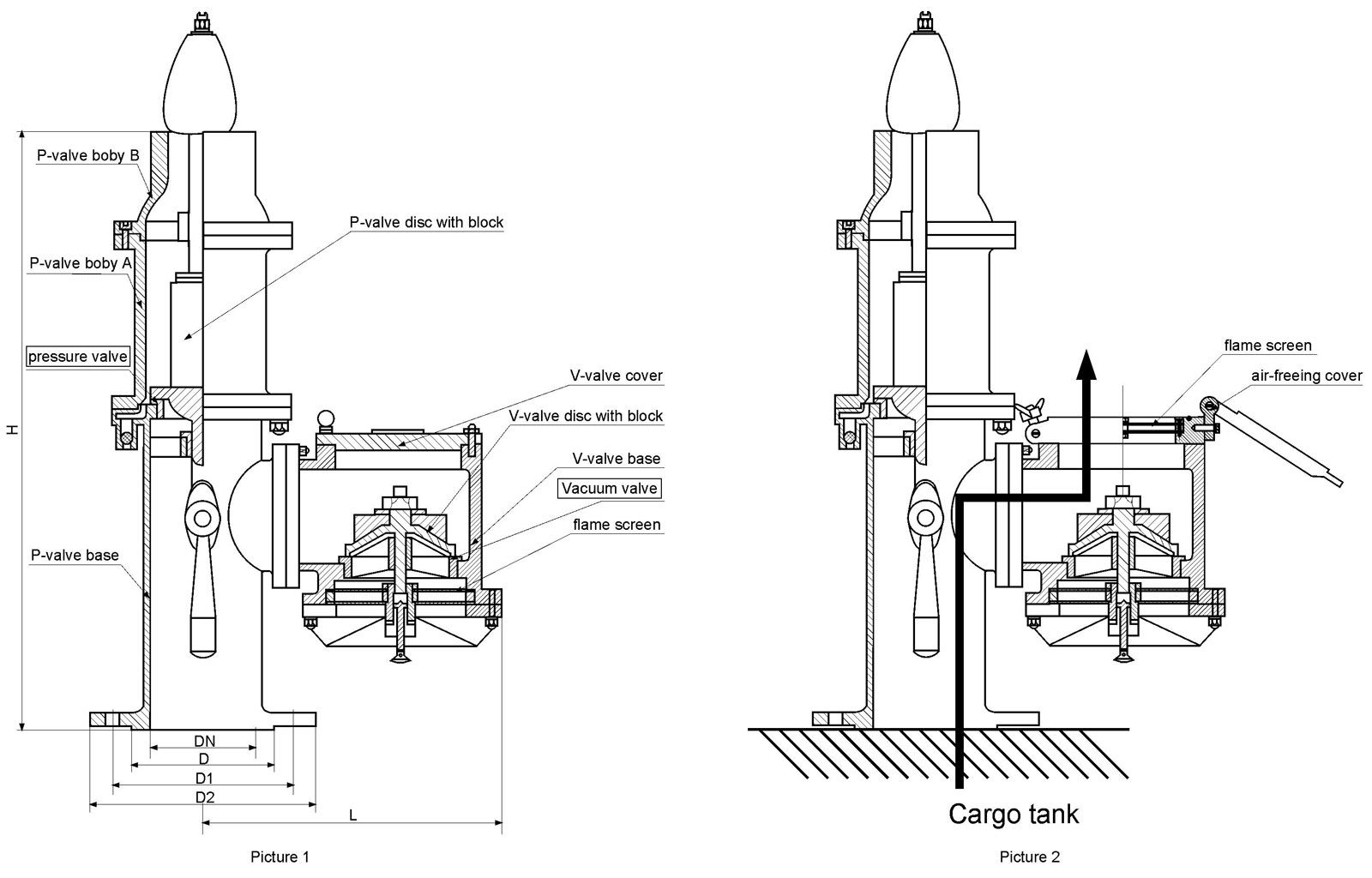
Picture 1 is the basic structure of the serial high velocity relief valve; Picture 2 is a high velocity relief valve with air-freeing cover; the pressure valve and vacuum valve in it is under the sealing situation. Table 1 is the basic structure and size of the serial high velocity relief valve.
4.2 working principle
Picture 3 is the working principle of high velocity relief and pressure valve. The standard joint of high velocity valve is connected with cargo tank, when the cargo tank is loading, the compressed air will formed, the pressure valve disc with block will automatically lift up, start and dropping in a flash while the compressed air meet to the operating pressure (oil tanker is 14.0 Kpa, chemical tanker is 20.0 Kpa) of P-valve of high velocity relief valve. The compressed air in the tank is as the arrowhead showed,it will relief to the atmosphere from cabin to the outlet through valve. At the same time, the interior pressure of valve will impact on the vacuum valve disc so that its sealing will be better.
Picture 4 is the main principle of vacuum valve. The vacuum (negative pressure) will formed when the tank unloading, and the valve will automatically open while the negative pressure reach to the open pressure (-3.5Kpa), at that time, the air will come into the cabin from deck space through flame screen, which as the arrowhead showed. The negative pressure will impact on the p-valve disc so that the sealing of pressure valve will be better.
Picture 2, workers only need to open the air-freeing cover on the vacuum valve, then the interior air of cabin will flow into the atmosphere through air-freeing cover and flame screen when cleaning the cargo tank and freeing the air.
ZGB – 1 BELLOW FLAME STOPPER
TECHNICAL PARAMETER
| MARK |
TYPE |
WEIGHT (kg) |
DIMENTION (mm) |
| D1 |
D |
L |
H |
nxd |
| ZGB(I)-50 |
DN50 |
6 |
Ф110 |
Ф140 |
220 |
235 |
4x14 |
| ZGB(I)-100 |
DN100 |
20 |
Ф170 |
Ф205 |
325 |
275 |
4x18 |
| ZGB(I)-150 |
DN150 |
25 |
Ф225 |
Ф260 |
425 |
290 |
8x18 |
| ZGB(I)-200 |
DN200 |
35 |
Ф180 |
Ф315 |
495 |
305 |
8x18 |
| ZGB(I)-250 |
DN250 |
46 |
Ф335 |
Ф370 |
595 |
320 |
12x18 |
The Instruction For The Use Of ZGB-1 Bellow Flame Stopper
The Characteristics:
- The new type of bellow flame stopper is a renewed production in 1996, and it is the safety anti-flame equipment necessary for the oil storage.
- The product is tested by the professional institution under the Ministry of Public Security, and it is in accordance with the requisition of GB5908-86
- The material of the casing is Al-alloy, which is light in weight and easy to test and repair, and is convenient to install.
- The material of the stopper layer is stainless steel, which is better to anti-corrosiveness.
The Properties:
- It is qualified in the anti-explosion, it has been tested by 13 times, and every time it can stop the flame.
- It is qualified in anti-burning, and when it is burnt for hours, it is no returning flame.
- It is qualified in water pressure test, and under the pressure of 0.6Mpa, it has no leakage. The Places And Situations For Use
- It is suitable for the A-type oils whose flash point is lower than 28°C or the B-type oils whose flash point is lower than 60°C, such as gasoline, light diesel, coal oil and crude oil.
- It can be used with the breathing valve, also it can be used separately.
- It can be used on the vent pipe inside of the oil tanker.
Operating Instructions
I. Standard, Purposes and main performance
Ventilating system of cargo tank plays an important role in fireproofing safety of oil tanker and chemical tank. IMO has approved amending the Article 59, Chapter II-2 of SOLA Pact, which about ventilating system of cargo cabin on oil tanker in 1996. That is force to adopt a redundancy ventilating method—add a series of ventilating auxiliary device (set two series of ventilating device or a series of ventilating device and a series of liquid pressure sensor on each cargo cabin), improve the existing ventilating system so as to avoid the liquid cargo over-pressure or loss-pressure. Additional, IMOMSC/Circ.1009 circulars (the Amendment about revised standard (MSC/Circ.667) of Design, Testing and Installation for preventing flame from entering into cargo cabin on oil tanker) has been approved at the 74th Session of IMO Maritime Safety Committee, amend the Section 1.2.4 of MSC/Circ.667 about design, testing and installation for preventing flame from entering into cargo cabin on oil tanker, the ventilating device shall be tested and installed not only according to the revised standard MSC/Circs.667, but also meet to the Standard ISO15364-2000 about shipping and maritime technique: pressure/vacuum valve on cargo tank.
The main spirits of ISO standard 15364 is give some improving suggestions to ship-owner, dockyard, institute of ship design and etc. on oil tanker and chemical tanker over-pressure or loss-pressure, clarify the responsibility and obligation of above-mentioned parties and manufactory of ventilating system, put forward new requirements about mechanical performance of pressure/vacuum valve and its maintenance, etc.
Pressure/vacuum valve is an important control ventilating system on cargo tank, also named as high velocity relief or P/V valve. The pressure valve in the high velocity relief valve will open when loading the liquid cargo or ballasting, then jet out combustible liquid cargo/air-mixture of liquid cargo tank with the rate of more than 30 m/s, and dilute in the atmosphere so that it will never drop on the deck; The vacuum valve in the high velocity relief valve will open when unloading the liquid cargo, then supply air to cabin safely so as to avoid the cabin is over-vacuumed; the high velocity relief valve can automatically adjust the pressure in the cabin as the changes of temperature when the tank navigate on the sea.
Our company has rich experience in manufacturing high velocity relief valve. Recently, we improve the manufacture of pure gravity high velocity relief valve under the support of some institutes of ship design and colleges.
Our company researched, designed and manufactured the CF-type high velocity relief valve is the new generation, which has approved by the state administrative organs about the test and type of pressure/vacuum valve. At present, high velocity relief valves, which manufactured by our company has been tested, there are: 1. fire-proof test; 2. re-burning test; 3. frozen test; 4. corrosion test; 5. flow rate and performance test. The valve will open only for the system pressure reach to the open pressure steadily, because of its special design. Generally speaking, one of the most advanced high velocity relief valve that is adopted in the world is the valve, which can lessen pipe diameter and decrease the vapor loss during the navigation. Our products not only meet to the IMOMSC/Circ.1009 circulars, reach to the requirements of ISO STANDARD 15364, but also improve the mechanical performance of high velocity relief valve to a higher level. In other words, there is no pounding phenomenon, no flutter or ripple when open or close it, or increase or decrease the pipe pressure, so that there is no re-burning phenomenon.
II. Basic structure and main parts and fittings of CF-type high velocity relief valve
II. 2 Main size parameter of CF-type high velocity relief valve, see table 1
table 1
| 8 |
250 |
320 |
350 |
395 |
460 |
730 |
12XФ22 |
| 7 |
200 |
258 |
295 |
340 |
455 |
730 |
8ХФ18 |
| 6 |
150 |
202 |
225 |
265 |
385 |
670 |
8ХФ18 |
| 5 |
125 |
178 |
200 |
240 |
380 |
665 |
8ХФ18 |
| 4 |
100 |
148 |
170 |
210 |
285 |
485 |
4ХФ18 |
| 3 |
80 |
128 |
150 |
190 |
285 |
460 |
4ХФ18 |
| 2 |
65 |
110 |
130 |
160 |
255 |
410 |
4ХФ14 |
| 1 |
50 |
90 |
110 |
140 |
255 |
410 |
4ХФ14 |
| serial No. |
DN |
D |
D1 |
D2 |
L |
H |
assembly hole |
Remarks: flange executive standard: GB2501-89, DN50-DN150, nominal pressure is 0.6Mpa; DN200?DN250, nominal pressure is 1.6Mpa(is equal to ISO2084-1974?ISO2441-1975)
II. 3 Main parts and fittings of CF-type high velocity relief valve, see table 2.
table 2
| serial No. |
descripton |
quantity |
material |
remarks |
| 1 |
P-valve base |
1 |
ZG200-400 |
|
| 2 |
water nozzle |
1 |
0Cr19Ni9 |
|
| 3 |
P-valve seat |
1 |
0Cr19Ni9 |
|
| 4 |
P-valve disc |
1 |
0Cr19Ni9 |
|
| 5 |
matching block |
1 |
0Cr19Ni9 |
|
| 6 |
P-valve boby (A) (B) |
1 |
ZG200-400 |
|
| 7 |
condukting machine |
1 |
0Cr19Ni9 |
|
| 8 |
handle |
1 |
0Cr19Ni9 |
|
| 9 |
V-valve boby |
1 |
ZG200-400 |
|
| 10 |
matching block |
1 |
0Cr19Ni9 |
|
| 11 |
V-valve disc |
1 |
ZG0Cr19Ni9 |
|
| 12 |
V-valve seat |
1 |
ZG0Cr19Ni9 |
|
| 13 |
flame screen |
1 |
0Cr19Ni9 |
|
| 14 |
flame screen gland |
1 |
ZG200-400 |
|
| 15 |
nameplate |
1 |
cooper |
|
| 16 |
climbing pole |
1 |
0Cr19Ni9 |
|
| 17 |
air-freeing cover or V-valve cover |
1 |
ZG200-400 |
|
Remarks: about the body material, ship-owner can adopt cast steel, 304 cast, 304L cast or 316L cast.
III. Installation of high velocity relief valve
Each valve will be provided as a whole, and each valve is adjusted and tested so that the working pressure of pressure valve and the open pressure of vacuum valve reach to designed standard. Workers only need to connect each flange of valve to ventilating pipe of cargo tank by bolt before operate.
IV. Operation of high velocity relief valve
IV. 1 Oil loading: pressure valve of CF-type high velocity relief valve is under operation. Before loading oil, the handle must be shifted to upper in clockwise direction through shift fitting 8, lift up the valve kits and then shift back, the valve kits can fall down so as to check the flexibility of valve kits.
IV. 2 Oil unloading: vacuum valve of CF-type high velocity relief valve is under operation. Before unloading, the climbing pole shall lift up the valve and then drop by fitting 16, do it some times so as to check the flexibility of the valve.
V. Installation of high velocity relief valve
It shall adopt the following maintenance and repair terms about the high velocity valve according to regulations: the valve kits must be maintained and repaired after 6 months so as to keep its normal performance. Valve kits also shall be disassembled for cleaning.
It shall be maintained and cleaned if it loads cargos frequently or the cargos are diversity.
To maintain and repair the valve:
5.1 disassemble the pressure valve for cleaning:
5.1.1 assemble the bolt (hex socket cap screw) on the top of fitting 7, lift up fitting 7 conducting machine.
5.1.2 assemble the connection bolt (hex socket cap screw or wing screw) of fitting 6, lift up fitting 6 P-valve body, clean the hole of it.
5.1.3 lift up valve pole on the fitting 4 and fitting 5, clean the P-valve body. Especially, the connection space between fitting 3 valve seat and fitting 4 valve disc, check if there is damage or flaw, and clean the hole of P-valve base.
5.1.4 fitting 4 and fitting 5 is a combination parts, do not loose or disassemble the set screw when cleaning;
5.1.5 all disassembled fittings shall keep separately, the valve body cannot operate smoothly if there is any damages;
5.1.6 assemble the fittings in opposite after checking and cleaning. Check it follow words which mentioned in the 4.1;
5.2 disassembling and cleaning procedures of vacuum valve
5.2.1 disassemble the wing screw and fastened bolt on fitting valve cover, lift up the valve cover;
5.2.2 lift fitting 10 and 11, take the fitting 11 V-valve disc out of valve body for cleaning. At the same time, clean and repair the interior of valve, especially the sealing space of valve. It also should check whether there is any damages or flaws on the connection space between fitting 11 and fitting 12.
5.2.3 general speaking, clean the dust on the flame screen from exterior. It only need to disassemble fitting 14 connection screw for taking the flame screen out, then clean it;
5.2.4 assemble the fittings in opposite after checking and cleaning. Check it follow the words which mentioned in the 4.2; check it first and then fix fitting 14 valve cover is also ok.
5.3 attention
5.3.1 the disassembled fittings shall put on the soft mat reasonably, and disassembled follow the procedure strictly;
5.3.2 use gauze with detergent for cleaning, and clear the dirt away from valve body.
5.3.3 check the valve; it must be sent to the manufacturer for repairing if it cannot performance smoothly;
5.3.4 the manufacturer adjusted and tested the open pressure of the vacuum valve and kits of pressure valve strictly, it must be sent to the manufacturer for adjusting the open pressure if it is necessary.
VI. High velocity relief valve with air-freeing cover
VI. 1 Main purposes of air-freeing cover
The valve will automatically open and eject to the upper of deck with the speed of 30m/s while the freeing gas in the tank reach to the open pressure of high velocity relief valve. The inner pressure of the tank cannot automatically open the high velocity relief valve while cleaning, exhausting. It need a manual device for its ventilating, such ventilating device is a air-freeing cover. It can be installed in the V-valve body of high velocity relief valve (see Picture 2), or be installed separately in the branch pipe of high velocity relief valve (see Picture 3).
Generally, the gas exhausted from air-freeing cover is incombustible. The air-freeing cover shall be closed when the ship navigating or loading for the working pressure is too low (less than 2.0 Kpa) and the flow rate is less than 20m/s.
As a fire arrester to prevent the pipe end from deflagrating, the air-freeing cover has been tested according to the regulations of EN12874-2001 and MSC/circ.667.
VI. 2 Main structure of air-freeing cover
The air-freeing cover is installed in the vacuum valve by bolt. it is composed of flame screen, shell and upper cover. (To see Picture 2).
VI. 3 Usage and maintenance of air-freeing cover
Ventilate the tank: loose the lock nut, lift up the upper cover and turn it to the vertical direction, then do the cleaning;.
The lock nut, hinge and flame screen is made of high quality stainless steel, keep its cleanness during operation, and clean it regularly.
Clean the interior of vacuum valve: disassemble the connection bolt and move the air-freeing cover, then do the cleaning.
List of Main Performance and Specifications
I. Manufacture and experimental basis:
IMO.MSC/Circ.677 Revised Standards of Designing, Testing and Installation the Device that can Stop the Flame into the Liquid Cargo Tank;
ISO15364: 2000 Pressure/Vacuum Valve for Cargo Tank;
IMO.MSC/Circ1009 Amendment about Revised Standards MSC/Circ.677 of Designing, Testing and Installation the Device that can stop the Flame into the Liquid Cargo Tank;
Section 5, Chapter 1 of Rules and Regulations for the Construction and Classification of Steel Ships 2001;
EN12874-2001, Performance Requirements, Testing Methods and Usage Scope of Flame Arrester;
Article 59, Chapter 11-2 of the International Convention for the Safety of Life At Sea, 1997 (SOLAS)
II.Main specification:
CF50, CF65, CF80, CF100, CF125, CF150, CF200, CF250
III.Main performance:
III.1.fire-resistance test and re-burning test on pressure valve and vacuum valve;
III.2.open and close the pressure valve and vacuum valve in the operating pressure range;
III.3.It must keep tightness of the shell of valve body from main pressure zone to main valve seat;
III.4.It must keep the shell, fitting and seal can bear the maximum pressure and temperature under normal working conditions and test its pressure according to the standard;
III.5.the design of interior structure of pressure/vacuum valve, it can disassemble when check, clean, maintain and change the interior fittings. If disassemble the whole device from system, it may appear some mistakes;
III.6.the equipment shall be operated under the normal temperature, if the equipment is icing, it will be operated after break the ice through using the manual device;
III.7.the valve disc, main axis of valve seat, flame screen shall use the seawater resistant, liquid resistant and vapor proof material; non-sealing fittings shall use the non-combustible materials; and the shell, bolts, washers and etc. shall use the material which meet to the national standard and do the anti-corrosion treatment;
III.8.pressure valve and vacuum valve shall be operated under the standard testing pressure.
IV. Main structure and working principle:
4.1 Main structure:
Serial high velocity relief valve adopts standardized design, each fittings and parts are standardized so that they can interchange and use for all purpose.
Picture 1 is the basic structure of the serial high velocity relief valve; Picture 2 is a high velocity relief valve with air-freeing cover; the pressure valve and vacuum valve in it is under the sealing situation. Table 1 is the basic structure and size of the serial high velocity relief valve.
4.2 working principle
Picture 3 is the working principle of high velocity relief and pressure valve. The standard joint of high velocity valve is connected with cargo tank, when the cargo tank is loading, the compressed air will formed, the pressure valve disc with block will automatically lift up, start and dropping in a flash while the compressed air meet to the operating pressure (oil tanker is 14.0 Kpa, chemical tanker is 20.0 Kpa) of P-valve of high velocity relief valve. The compressed air in the tank is as the arrowhead showed,it will relief to the atmosphere from cabin to the outlet through valve. At the same time, the interior pressure of valve will impact on the vacuum valve disc so that its sealing will be better.
Picture 4 is the main principle of vacuum valve. The vacuum (negative pressure) will formed when the tank unloading, and the valve will automatically open while the negative pressure reach to the open pressure (-3.5Kpa), at that time, the air will come into the cabin from deck space through flame screen, which as the arrowhead showed. The negative pressure will impact on the p-valve disc so that the sealing of pressure valve will be better.
Picture 2, workers only need to open the air-freeing cover on the vacuum valve, then the interior air of cabin will flow into the atmosphere through air-freeing cover and flame screen when cleaning the cargo tank and freeing the air.